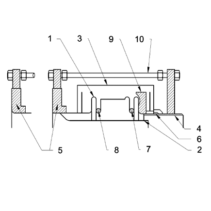
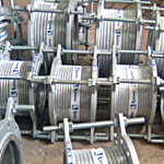
The most important component of an expansion joint assembly is the bellows. Additional components may also be incorporated in the design in order to compose more complex expansion joint assemblies fi t for the purpose. The following components are used to produce most of the attachments of expansion joints:.

1. Bellows
2. Liner
3. Cover
4. Weld-End
5. Flange
6. Collar
7. Hollow Reinforcing Ring
8. Solid Root Ring
9. Equalizing Ring
10. Limit Rod
1 – BELLOWS: Flexible components produced out of thin stainless steel and having single or multiple convolutions are called bellows.
2- LINER: The components minimizing the negative effects of the fl uids on the inner side of the bellows while fl owing through. In general they are used to prevent the abrasion on the inner surface of the bellows. Liners may be classified as single, conical or telescopic with respect to the design. Expansion joints with liners have to be installed with the proper orientation with respect to flow direction.
3- COVER: The components installed to protect bellows against the negative effects and improper operating conditions of the environment are called covers. The installation of covers is always recommended.
4- WELD-END: The components enabling the installation of expansion joints to pipelines by welding are called weld-ends.
5- FLANGE: The components enabling the installation of expansion joints to pipelines via bolts are called fl anges.
6- COLLAR: The ring-shaped components of proper thickness to strengthen the bellows in high pressure environments against expansion are called collars.
7- HOLLOW REINFORCING RING: These components mounted on the convolutions of the bellows strengthen the bellow components against internal high pressure.
8- SOLID ROOT RING: These components have the same functionality as the hollow reinforcing rings, however they are manufactured out of iron bars for increased strength.
9- EQUALIZING RING: These rings having the cross-section “T” are produced out of carbon steel, stainless steel or by iron casting. These rings limit displacement by the convolutions of the bellows due to the contraction, and increase the strength of the expansion joints against internal pressure.

10- LIMIT ROD: The components generally made of iron bars to distribute the axial movement to the bellows in Tied Universal Assemblies are called limit rods. Limit rods are NOT DESIGNED to limit the effects of the pressure at the bellows. They are designed to limit the (axial, lateral or angular) movements of the bellow under normal operating conditions. In other words they prevent the excessive expansion and contraction movements. They can also be used to keep the effects of the pressure at the bellows under control, by admitting the lateral movements only. Generally they are made of iron bars. Angular movements are fi xed by two limit rods placed at right angle.

