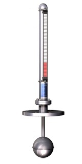
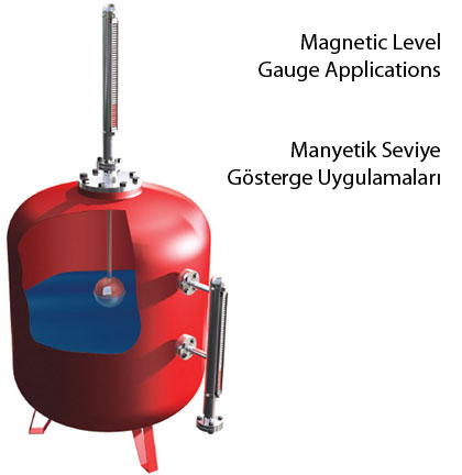
Magnetic level gauges are installed in the tanks in various ways, where it is supposed to measure the level of the liquid. The floater in the by-pass tube moves up and down with the fluid based on the principle of communicating vessels. The movement of the floater makes the bi-color magnetic disks placed in the aluminum profile to rotate around themselves. The magnet in the floater is situated at the same level as the liquid regarding the immersion depth of the floater. Thus the bi-color magnetic disks, which colors visible from outside are changed by the floater, indicate the liquid level exactly and precisely. The color of the magnetic disks, as seen from the outside, begins to turns to red when the liquid level ascends, and conversely turns to white when it descends. In this way the liquid level in the tank can be monitored correctly. Magnetic level gauges can also be used in automation systems as a data input device. The liquid in the tank can be monitored by height of the liquid level, the volume of the liquid in the tank, etc. Using switches equipments like pumps, solenoid valves, etc can be controlled. The information of liquid level can be transmitted to the automation systems by connecting a series of reed-switches and control panel hardware to the magnetic level gauges.

Technical Features

Lower Spacing
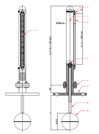
H=Float Length- 10 mm.
Flange Center Spacing
L=150 – 5500 mm.
Design Features
Design Pressure : 10 BAR
Design Temperature : – 20 + 150 C

1- Flange Connection : AISI 304
2- Pipe Clamp: AISI 304
3- Display Roller Unit : Alüminyum
4- Magnetic Rollers : Temperature Durable Special Plastic
5- Magnet System: Magnet
6- Bypass Pipe Flange Connection: St 37-2
7- Tank Connection Flange: DN 150 PN16 St 37-2
8- Buoyancy Tube: AISI 304
9- Float: AISI 316 L
Usage Area
· Chemical Storage Tanks
· Steam Boilers
· Gasoline Tanks
· Undereground Tanks
· Acid Tanks
Advantages
· Continuous & Easy Monitoring
· A Leakproof Design
· Flange Connection In International Norms (ANSI,DIN etc.)
· Operational with various medias.
· High Temperature & Pressure Resistance
· Long Lasting
Media
· Petroleum Produtcs
· Water, Wastewater, seawater
· Acids
· Gas (As Liquid)
· Caustic Materials
· Foam (As Liquid)
Special Note
Carbon steel parts of all magnetic level gauges are cadmium-plated. Products are under our 2 years quarantee for factory faults. For special requirements please consult us. Please see Useful technical tables pages for flange and pipe size tables. Pleasee consult us for abrasive medias.
YOU CAN MONITOR THE CHANGE OF THE LIQUID LEVEL IN YOUR (UNDERGROUND) TANK VISUALLY FROM THE TOP BY USING KRS-139S OVERTANK TYPE MAGNETIC LEVEL GAUGES, WHERE ONLY INSTALLATION FROM TOP OF THE TANK IS POSSIBLE.
Simple Problems Occuring After Installations & During Operation Of Magnetic Level Gauges & Their Solutions
| PROBLEM | REASON | SOLUTION |
| Indication of the liquid level as white and not red. | The reason of indicating the liquid level with a wrong color is the upside down installation of the display. | Dismount display panel, turn it upside down, and reinstall it to the device. |
| Indication of a wrong liquid level. | The floater can be sticked with high density fluids, and jammed. | Dismount the floater, clean it, and reinstall it. |
| The floater may be sticked by some materials having slipped into the by-pass tube. | Dismount the floater, clean it, and reinstall it. | |
| The floater may be damaged or broke down. | Dismount the floater, remove impurities from inside of the tube, and reinstall it. | |
| The floater may be put into the by-pass tube upside down. | Dismount the floater, turn the direction of the floater in accord with the direction sign on it, and reinstall it. | |
| No level change has been observed at the tankwhere the device is installed. | Floater missing. | Install floater. |
| The floater can be sticked with high density fluids, and jammed. | Dismount the floater, clean it, and reinstall it. | |
| The floater may be sticked by some materials having slipped into the by-pass tube. | Dismount the floater, remove impurities from inside of the tube, and reinstall it. | |
| The floater may be damaged or broke down. | Replace the floater, install a new floater. | |
| The floater may be put into the by-pass tube upside down. | Dismount the floater, turn the direction of the floater in accord with the direction sign on it, and reinstall it. | |
| The disks in the display panel may be clamped or even squeezed by the clamps more than required. | Reinstall them in accord with the Hardware Installation Instructions Manual. |
Assembly On Horizontal & Vertical Tanks


