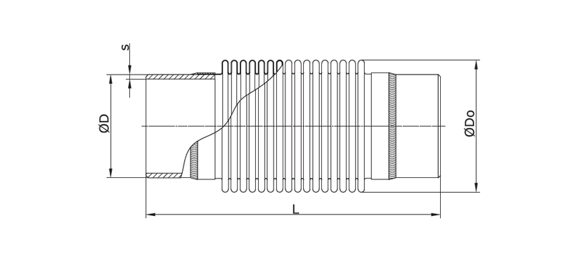
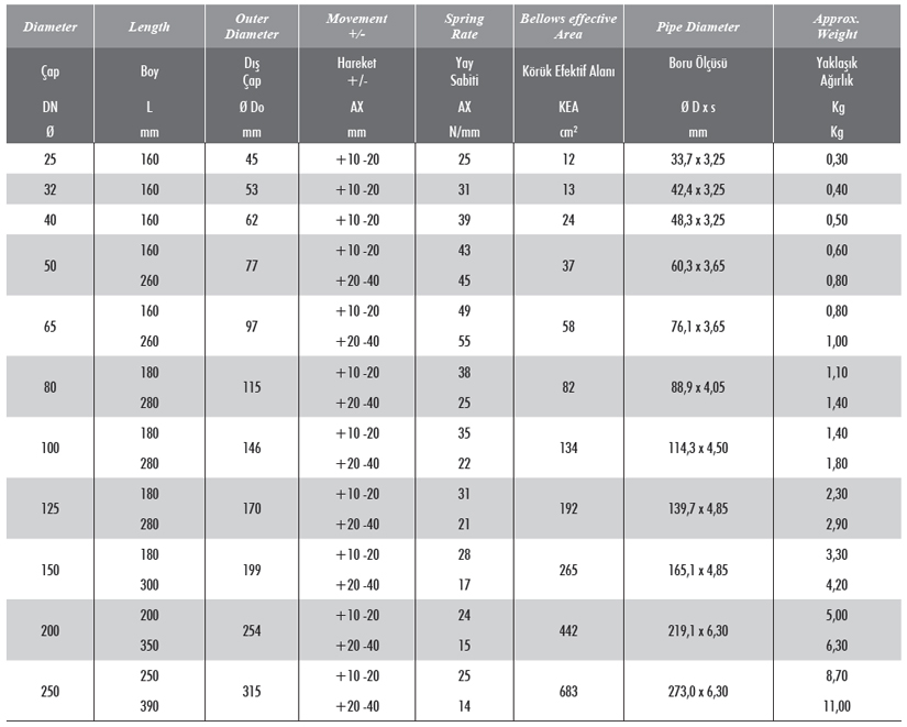
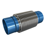
KRS-3 Weldend expansion joints are used to absorb the thermal expansion parallel to the axis of the straight pipelines. Long piping systems are divided into shorter expanding sections, and isolated by main anchors. Thus the movements in the individual expanding sections are absorbed by the KRS-3 axial expansion joints in this section.
Bellow Features
Standard Production : AISI 321 (DIN 1.4541)
Special Production : AISI 304 (DIN 1.4541), AISI 309 (DIN 1.4828), AISI 316 (DIN 1.4401), AISI 316 ti (DIN 1.4571) etc
Design Information :
Design Pressure : 16 BAR
Design Temperature : – 196 + 550 C
Weld End Features :
Standard Weldend : Rst 37-2 (DIN 1.0038)
Special Weldend : Stainless Steel etc.
Liner Features :
Standard Liner : AISI 321 (DIN 1.4541)
Special Liner : AISI 304 (DIN 1.4541), AISI 309 (DIN 1.4828), AISI 316 (DIN 1.4401), AISI 316 ti (DIN 1.4571) etc
Applications
For absorbing axial movement, For reducing tension and noise, All machines, All pumps, All motors, Industrial applications, Exhaust systems, Gas and water lines, Drinking water lines, etc.
Painting Information
All weldends and pipe parts in all diameters are with special paint ( for corrossion protection).
Special Note
Design temperature can be designed until + 950 C as well.Products are under our 2 years quarantee for factory faults. For special requirements please consult us. Please see Useful technical tables pages for flange and pipe size tables.Use liner to protect bellow from wear due to abrasive media.


What Is Axial Movement ?

The movements of expansion or contraction parallel to the axis of the bellows are called axial movements. KRS-14 Axial expansion joints are used to absorb the thermal expansion parallel to the axis of the straight pipelines. Long piping systems are divided into shorter expanding sections, and isolated by main anchors. Thus the movements in the individual expanding sections are absorbed by the KRS-6 axial expansion joints in this section.
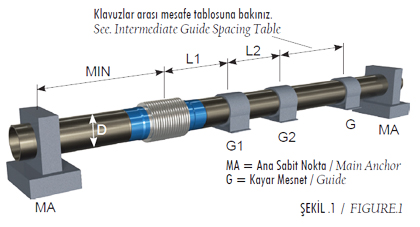
FIGURE 1: This figure shows the simplest and most basic application of an axial expansion joint. The sequence of installation steps to pay attention to follows:
1. Only one expansion joint may be installed between two main anchors.
2. Main anchors are located in the direction of pipeline.
3. An expansion joint is located next to each main anchor.
4. The fi rst pipe alignment guide is located within the distance of 4 pipe diameters next to the axial expansion joint.
5. The second pipe alignment guide is located within the distance of 14 pipe diameters next to the fi rst pipe alignment guide.
6. The distances between the other pipe alignment guides to be located are determined according to the Pipe Guide Spacing Chart by EJMA (Expansion Joint Manufacturers Association).


