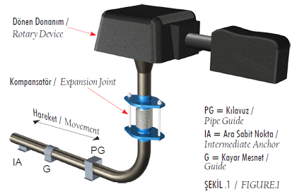
FIGURE 1: As depicted in the fi gure, pressure thrust is compensated by using limit rods installed at lateral expansion joints and intermediate anchors are used instead of main anchors. A planer pipe guide is used providing the thermal expansion in the vertical pipe leg to be taken as natural fl exibility in the horizontal pipe run.

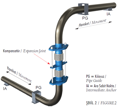
FIGURE 2: As depicted in the fi gure, the big amount of the thermal expansion in the pipeline precludes the usage of single-bellow lateral expansion joints. In these instances it is possible to absorb the expansion by using double-bellowed lateral expansion joints. This type of assemblies is mainly used to protect turbines, pumps or compressors.

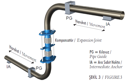
FIGURE 3: As depicted in the fi gure, axial movement at the horizontal pipe run is provided to be absorbed by the bellows by installing doublebellowed lateral expansion joints on the vertical pipe leg. Incases like this, keeping the distance between two bellows as long as possible is the best solution. Installation of the expansion joint as described above results in low offset forces on adjacent equipments.


